Stud welding process
Capacitor discharge stud welding (CD)
CD
Capacitor Discharge (CD) stud welding with tip ignition
HBS stud welding units provide outstanding reductions in costs and
time. Every weld is precise avoiding any need for post treatment.
Contact or gap
In contrast
to contact welding, with gap welding the stud is positioned at a defined
distance shortly before welding starts. This creates a higher plunging
speed which leads to a shorter welding time (only 1 ms!).
This characteristic also allows welding of touchy materials like e.g. aluminium and brass.

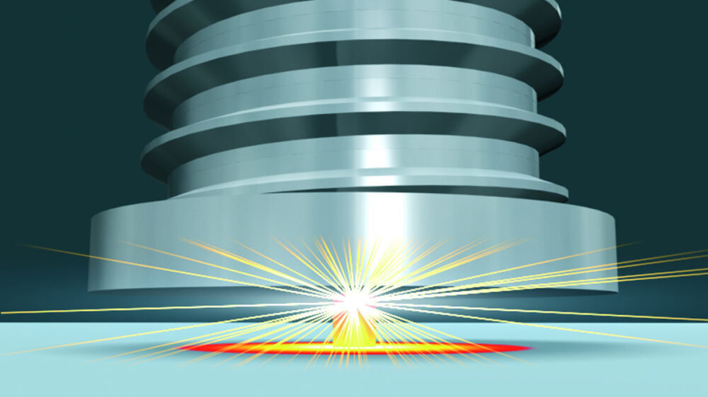


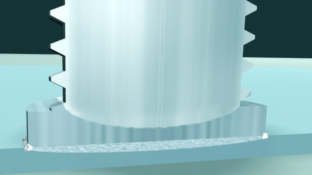
Capacitor discharge stud welding with contact

- The capacitor battery will be charged according to chosen charging voltage.
- The stud (with ignition tip) is placed onto the work piece and pressed by a spring in the welding gun onto the work piece (contact). The current circuit is closed.
- After triggering the welding process, the rapidly increasing current evaporates the ignition tip and ignites the arc.
- Stud and work piece are melted.
- The stud is moved forward to the plate.
- The arc is cut as soon as the stud touches the work piece.
- The molten zones are joining and solidifying.
- Welding time is ≤ 3 msec.
- Recommended plate thickness should be 1/10 d, but not less than 0.5 mm.
Capacitor discharge stud welding with gap

Gap welding is different from the procedure described above: Before welding starts, the stud is positioned in a defined and adjustable distance above the work piece (gap). After triggering the welding process, the stud is accelerated by a spring to the plate surface. If there is contact between the ignition tip on the work piece, the process continues as described above. Welding time is approx. 1 msec; thus e.g. welding of aluminum becomes feasible without using a shielding gas atmosphere. Recommended plate thickness should be 1/10 d, but not less than 0.5 mm.
Examples of applications capacitor discharge stud welding (CD)
Typical applications include: Sheet metalwork, electronic industries, switchboard cabinets, laboratory and medical equipment, food industry, household appliances, etc. When studs are welded to thin sheets (steel, aluminium and brass), the procedure of tip ignition will always be the most cost effective process and sometimes the only solution.





Drawn arc stud welding (ARC)
ARC
Drawn arc (ARC) stud welding with ceramic ferrule or shielding gas
The process drawn arc stud welding is mostly used for stud diameters of 3 to 25 mm and a welding time of 100 to 1 500 ms.
Drawn arc stud welding with ceramic ferrule is recommended for studs with diameter of more than 12 mm. If it is required to protect the weld pool from atmosphere, shielding gas should be used. This process variant is also used with automated applications.
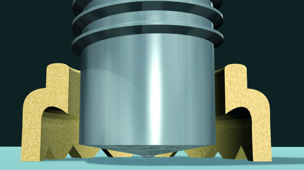

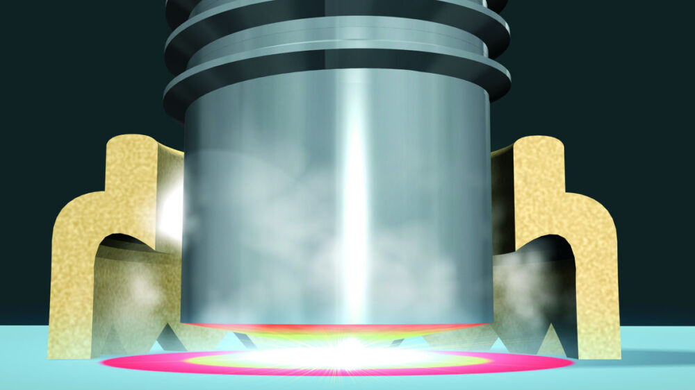
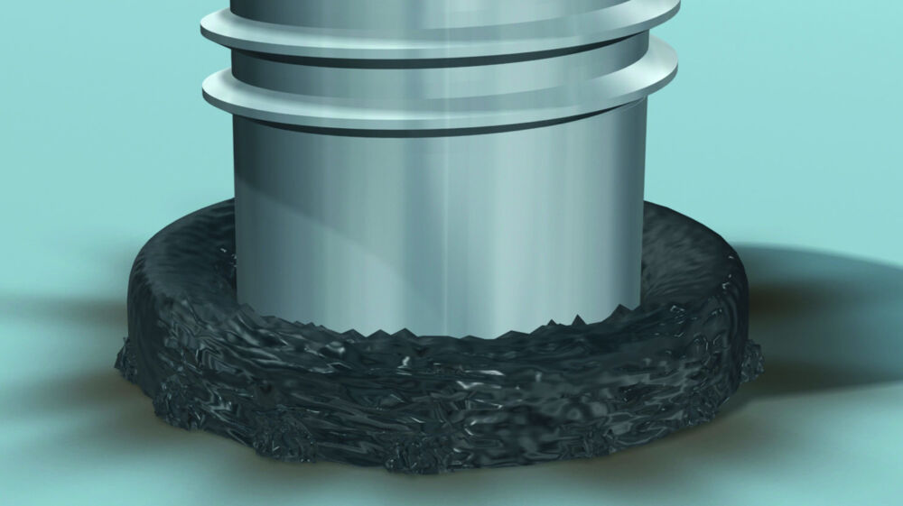
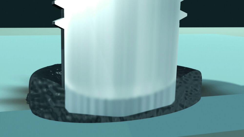
Drawn arc stud welding with ceramic ferrule or shielding gas
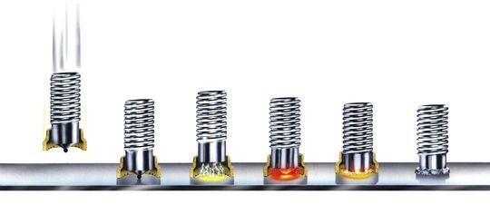
- The stud is inserted into the chuck and - if necessary - equipped with a ceramic ferrule.
- The stud is placed onto the work piece.
- A lift mechanism in the welding gun or welding head lifts the stud. A secondary arc (pilot arc) of low current is ignited between stud tip and work piece.
- Then the ignition of the main arc is carried out between stud tip and work piece.
- Stud and work piece are melted.
- At the end of the adjusted welding time the stud is moved to the work piece, the two molten zones join. The power source is switched off, the weld pool solidifies and cools down.
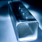
Examples of applications drawn arc stud welding (ARC)
ARC Drawn arc stud welding with ceramic ferrule, shielding gas or without.
Specifically designed for thicker sheets of about 2 mm or higher.
Application ranges: steel construction, engineering construction, shipbuilding industry, vehicle construction, structural and civil engineering.




Short cycle stud welding (SC)
SC
Short Cycle (SC) drawn arc stud welding
High current, shorter duration of welding time
The welding sequence is the same as the sequence of drawn arc welding (ARC), however, with relatively higher currents and shorter welding times (max. 100 ms). The short cycle drawn arc stud welding is suitable for stud diameters up to 16 mm on thin metal sheets.
Without shielding gas
Up to 8 mm stud diameter, the process is often carried out without
weld pool protection. Normally studs with flange are used to achieve
high tensile strengths in spite of pores in the weld zone.
The short cycle process is especially suitable for welding of material combinations like steel (base material), stainless steel (stud) as well as aluminium. To achieve a high welding quality, use of shielding gas is recommended.


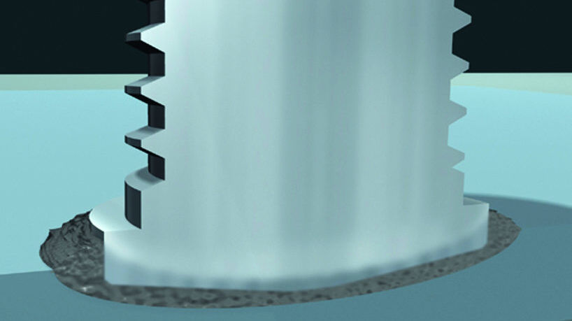
Short cycle drawn arc stud welding
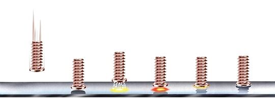
- Welding sequence is as with drawn arc stud welding (ARC) with the exception of higher current and shorter welding time (≤ 100 msec).
- This variant is suitable for stud diameters of up to 12 mm to thin plates.
- As the process up to 8 mm is often used without weld pool protection, studs with upset flange are used. In this way, a higher tensile strength of the weld zone is achieved in the welded area than in the stud shaft in spite of the existence of pores.
- From 8 mm stud diameter upwards, a shielding gas should be used to avoid pore formation.
Examples of applications short-cycle stud welding (SC)
With ARC and IT stud welding units for short cycle drawn arc stud welding (with and without shielding gas).
Multiple applications with: studs, tapped pads and pins onto thin metal sheets. A wide field of application is in vehicle construction, in particular using christmas tree studs to fasten conduits and trims





ISO - Insulation technique - Welding processes for insulation
Cupped head pin welding ISO Plus (HVAC)

The welding process of cupped head pin welding corresponds with the contact-type capacitor discharge drawn-arc stud welding (CD).
HVAC - Fasteners for heating, ventilation and air-conditioning
If you want to fasten insulation mats in a fast and cost efficient way, you should use ISO-PLUS cupped head pins. With this procedure, you fasten the insulation mat to the base material in one process step. This perfect fastening procedure replaces the very complicated traditional procedure: weld on a pin, push the mat over the pin, put on the clip and then cut the projecting tip or bend it.

Fire-resistant insulation with ARC-insulation pins (FRI)
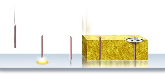
The welding process of ARC-insulation pin welding corresponds with short cycle drawn arc stud welding (SC).
FRI - Fire-Resistant insulation
HBS in use! For example: Thermal power stations with incineration
plants, industrial furnaces, chemical and petrochemical industries.
Optimum fastening of fire resistant insulation with special pins and
clips. For outstanding protection of steel structures against high
temperature (up to 1250°C) and corrosion.

Nut Welding (MARC)
MARC
Innovative ARC welding technique
HBS presents MARC, a manual nut welding system which is more and more replacing traditional processes all over the world due to the innovative procedure with a magnetic rotating ARC.
Regardless of whether only static stability is required or if additional, customerspecific connection properties (e.g., pressure tight) need to be fulfilled, you always achieve the best results - with considerable time and cost savings.
Spatter free joints can be achieved with a high welding cycle time of
up to 10 welds/minute. This is especially suited for thin metal sheets
from 1 mm upwards.
MARC provides the access to a new future to international trusts, medium-sized companies as well as to crafts enterprise.


MARC - MAGNETIC ROTATING ARC - Nut Welding with rotating arc

Functional welding sequence:
- The nut is placed onto the base material - the current circuit is closed
- Preflow of shielding gas
- Coil current is switched on and magnetic field is generated
- Power unit is switched on and arc voltage is provided
- Lift of nut/sleeve
- Ignition of pilot arc and then ignition of welding arc between nut and plate
- Burning of rotating arc along the ring-shaped welding area
- At the end of welding time, the nut is lowered and plunged into the liquid weld pool
- Electrical short-circuit and cut-off of welding current
- Formation and solidification of weld seam with post-flow time of shielding gas
Examples of applications nut welding (MARC)
Welding on pads and nuts on punched and unpunched metal sheets.
Applications are e.g. sprinkler systems, ventilation tubes, hinges, pressure vessels, exhaust systems.


